Computational Fluid Dynamics
Computational Fluid Dynamics is a detailed examination of air and thermal movement in or around a building. CFD simulations are typically performed for sections of a building, for example to study air and temperature distribution, downdraught at a glazed façade, or a contaminant such as vehicle exhaust. The area for study is divided up into a 3-D computational ‘mesh’ of very small finite volumes. The results give a detailed indication of air flow patterns and temperature distribution within a space. ‘Steady-state’ models are solved for one moment in time, for example the peak heating or cooling time. Transient CFD simulations are used to track the development of a contaminant (ie smoke) or the spread of heat when a device is switched on, but the length of simulations are measured in minutes and shouldn’t be confused with DSM simulations which are often run for a whole year. The detail of a CFD simulation allows air supply patterns to be modelled and matched to the distribution patterns of manufacturers specific products, giving confidence in the results.
Westfield Shopping Centre, White City
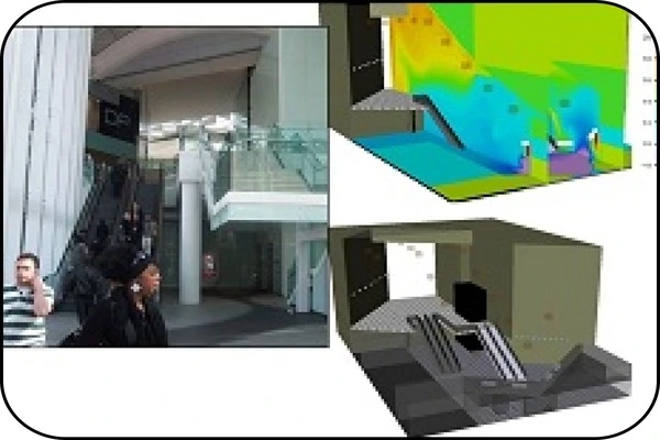
At Westfield Shopping Centre in London CFD modelling was used for detailed analysis of air distribution around the centre and entrance areas. A number of different supply devices including drum louvres, linear slots, swirls. nozzles and overdoor heaters were first accurately represented in CFD test cells before inclusion in 3-D models of selected areas of study. Results included air distribution, draughts and temperature profiles.
St Mary Axe, London (The ‘Can of Ham’)
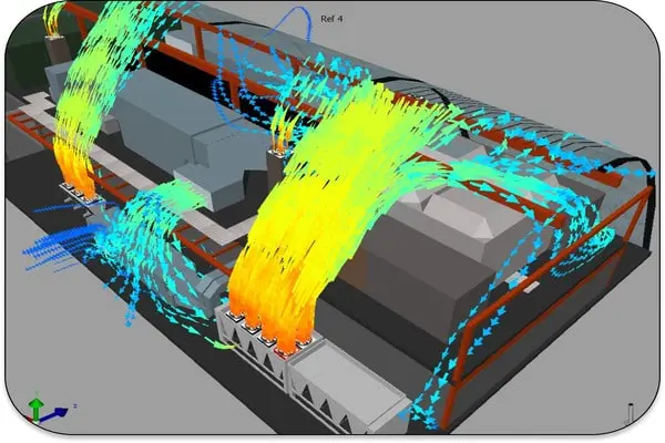
70 St Mary Axe is a high rise building in central London. Significant mechanical plant is located at roof level, with a specially designed roof cover. CFD was used to help with the spatial co-ordination of generators, dry air coolers, AC units and ventilation intakes/outlets to ensure that all systems operated within specification. Careful placement of equipment ensured that ventilation intakes were not contaminated with discharge air and heating/cooling plant did not recirculate discharge
Fume Cupboard Design Variation
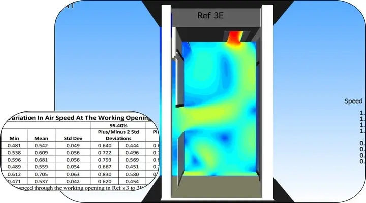
A 3D CFD model was constructed using FloVENT software to represent a standard design for a walk in fume cupboard with a rear baffle plate. The initial simulation produced air movement expected in a standard booth. Next a proposed bespoke design with rear opening doors and low level extract was simulated. The bespoke booth and five variations were simulated to assess measures to produce equal flow and to promote good flow at floor level for the removal of heavy vapours. The results were presented as visual plots and animations, together with statistical analysis.
Cooling Product in a Cold Store
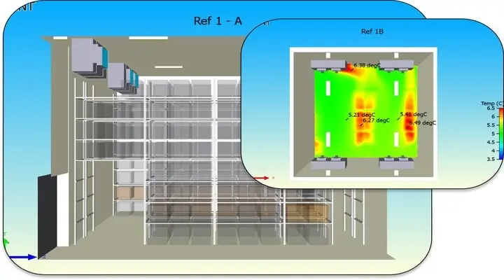
CFD Modelling was used to prove the design of refrigerated cool room which used powerful fans circulating chilled air. The model included the effect of adding warm product to the detailed layout of the storage racks. The chillers were modelled in a virtual test cell to match manufacturers data before including in the model. Contour plots with spot temperatures showed that good air circulation maintained the existing product at properly chilled temperature.
Car Park Ventilation
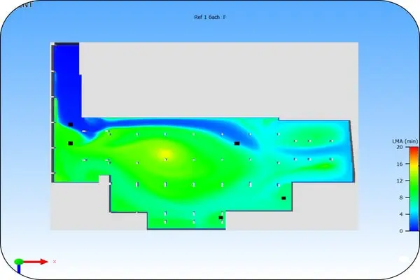
We have modelled a number of car park ventilation schemes, both mechanically and naturally ventilated. Analysis can either take the form of directly modelling CO emissions, based on known engine emission rates, and producing plots and tabulated CO data including the peak value and the 8 hour time-weighted average. Alternatively the ventilation may be modelled to produce values of the Local Mean Age (LMA) of air throughout the car park. Smoke clearance can be modelled transiently using Fire Dynamic Simulator (FDS) software.
Computational Basis
Building Performance uses Siemens FloVENT commercial specialist ventilation CFD software, openFOAM open source CFD software and Fire Dynamic Simulator (FDS) developed in the United States at the National Institute of Standards and Technology (NIST), FloVENT and openFOAM (FDS?) use the finite volume method of calculation based on conservation principles. Conservation of mass, momentum and energy. The domain under consideration is divided into small finite volumes (cells) representing a ‘field’ of values for each variable. From initial assigned values each cell is solved in turn based on it's own values and conditions in neighbouring cells. This changes the initial value to give something closer to the final result. The software uses mathematical techniques to estimate the remaining error from the calculation and uses it to make another run of calculations, repeating the process to improve the results. The process iterates until certain conditions are satisfied:
- The sum of the errors (residual) for each variable is reduced to the point of insignificance
- The values in individual cells change in insignificant amounts
- Mass balance is achieved (This generally needs confirming by the user). Once these conditions are met the simulation is said to have ‘converged’.
A fourth condition should be considered, that the results must make engineering as well as mathematical sense.
A steady-state simulation is run for one moment in time. Inputs do not vary with time and material properties may vary with space but are constant in time. While this is not realistic for most environments it can be helpul to show that designs work under steady conditions and it is computationally and analytically less demanding. Transient simulations are used when a staedy-state assumtion is not acceptable and have additional time terms in the equation sets. They answer time based questions, for example how long does smoke take to clear, or a heater take to warm the entire room.There are many texts on the subject, often addressing CFD from a particular viewpoint or field of application.Our suggested reading would include: C.J. Greenshields H.G. Weller First Edition 2022 Notes on Computational Fluid Dynamics: General Principles ©2022 CFD Direct Limited John D. Anderson, JR 1995 Computational Fluid Dynamics The Basics with Applications ©1995 McGraw-Hill, Inc. For further reading, downloads and information about OpenFOAM contact CFD Direct